voltage detection circuit Circuit Diagram
voltage detection circuit Circuit Diagram Consider the below image, where we need over-voltage protection for Microcontroller. The microcontroller can be anything that has a maximum rating of 5V across the IO pins. Therefore, more than 5V could damage the microcontroller. The Zener diode used in the above circuit is a 5.1V Zener diode. It will work fine during an over voltage situation. In some situations where the input voltage is higher than expected, we always use an overvoltage protection or crowbar protection circuit. The crowbar protection circuit is one of the most used overvoltage protection circuits. A power supply can fail in many ways; similarly, there can be many ways to protect a circuit from overvoltage.

Hence, in simple terms, the job of the Crowbar Circuit is to detect the overvoltage and blow the fuse (sometimes, a circuit breaker is tripped). Typically, Crowbar Circuits are designed using Thyristor (SCR) or TRIAC as the main shorting device. Crowbar Circuit Design An overvoltage protection circuit is a circuit which protects electronics from excess voltage, which could potentially damage or destroy electronic components. In this project, we will build a simple, yet effective, overvoltage protection circuit using a fuse and a zener diode, as the protecting elements, that will work for electronics that
How to design an overvoltage protection circuit? Circuit Diagram
A reference is just a low-current reference, it's not designed to power anything. It could be used as part of a protection circuit or part of an over-voltage detection circuit, or part of a regulated power supply, using a comparator to compare the actual power supply voltage with the reference. If you can't find the exact reference you want you
Here simple overvoltage protection circuit is designed by using a Zener diode and transistors. This protection circuit acts as a voltage regulator and also a circuit breaker. you can choose the Zener diode voltage range depending on your load or device voltage range, we have a 5V load and hence we have used a 5.1V Zener diode.
Simple Overvoltage Protection Circuit Circuit Diagram
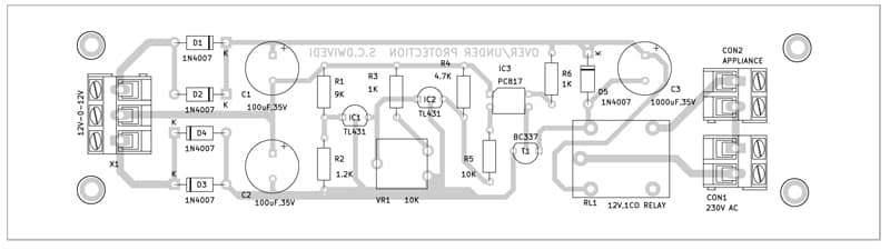
An automatic voltage regulator circuit is a handy electronic device that ensures a steady and optimum voltage supply, protecting the devices from damage caused by under or overvoltage scenarios. In this article, we will guide you through the process of building your own automatic voltage regulator circuit, complete with a detailed diagram.
