Test a simple electronic buzzer circuit Circuit Diagram
Test a simple electronic buzzer circuit Circuit Diagram The Circuit with all of the values of its resistor and capacitors set, when supplied with 9 Volts of battery, produces a buzzer sound. This IC NE555 drives an 8Ω to 25Ω loudspeaker to produce an audible square-wave tone. In addition to this, a Siren or 555 tone generator can be interchangeably used as a buzzer. Application A buzzer is a high frequency oscillator circuit designed to produce a buzzing sound via a transducer or speaker output. Simple Buzzer using a Single Transistor With just a single transistor, a ferrite inductor, and a piezo transducer, you can create a circuit that will "buzz" or, more accurately, "tweet" for you, potentially producing a

Today I am showing you how to make simple buzzing circuit Buzzer Circuits on a breadboard.I am in no way a expert in electrical engineering but I just wante

How to make a Buzzer at home Circuit Diagram
Simple Buzzer Circuit: The following items are required to build this circuit: 9-Volt Battery Snap 9-Volt Battery Two wires DC Buzzer Breadboard Projects Contests Teachers Simple Buzzer Circuit. By 624117 in Circuits Electronics. 7,039. 1. 2. Introduction: Simple Buzzer Circuit

The circuit design of the electronic buzzer shown is amazingly simple in design and yet is able to produce a sound output that's quite sharp to the ears. The construction procedure does not require much of explanation, as the whole circuit can be built within minutes with the help of the given schematic and the parts list.
Simple Buzzer Circuit : 3 Steps Circuit Diagram
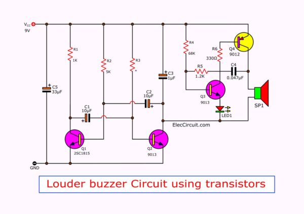
Figure 1: simple electronic buzzer circuit diagram using two-transistor. By has both resistors- R=1.2K and C=0.047uF to set the output frequency. Which can change slightly the value of both components, so the output sound changed. Making Buzzer circuit. This project uses a few components and is easy. So you can assemble them on a perforated A buzzer circuit is an electronic device that produces an audible sound when activated. Buzzer circuits are widely used in various applications, such as alarms, timers, and user interfaces. In this article, we will explore the basics of buzzer circuits, how to create a simple buzzer circuit, and ways to enhance the design for improved